-scaled-1.png )

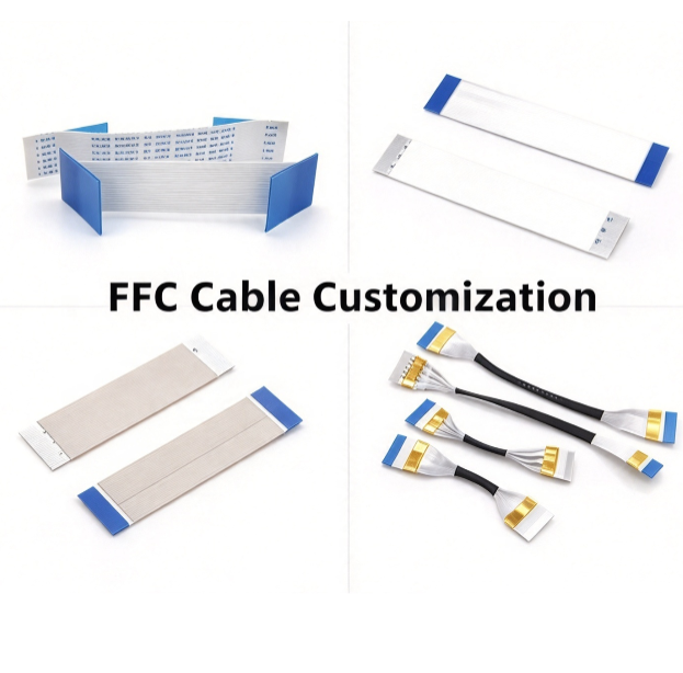
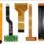
Not all FFC cables are the same. Beyond the standard flat ribbon, several custom processes change how the cable is built, handled, and installed. Here are the most common ones.
Split FFC (Individual Conductors)
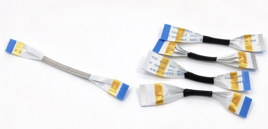
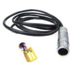
Instead of keeping all conductors bonded together across the full length, the FFC is split into individual conductors at one or both ends. The conductors remain laminated in the middle, but separate at the ends like loose wires.
Why use it:
- Each conductor can be routed independently
- Easier to terminate with individual connectors or solder points
- Reduces mechanical stress at the connection area
Typical applications: Camera modules, sensor arrays, multi-point connections
Black Rubber or Sleeve Protected FFC
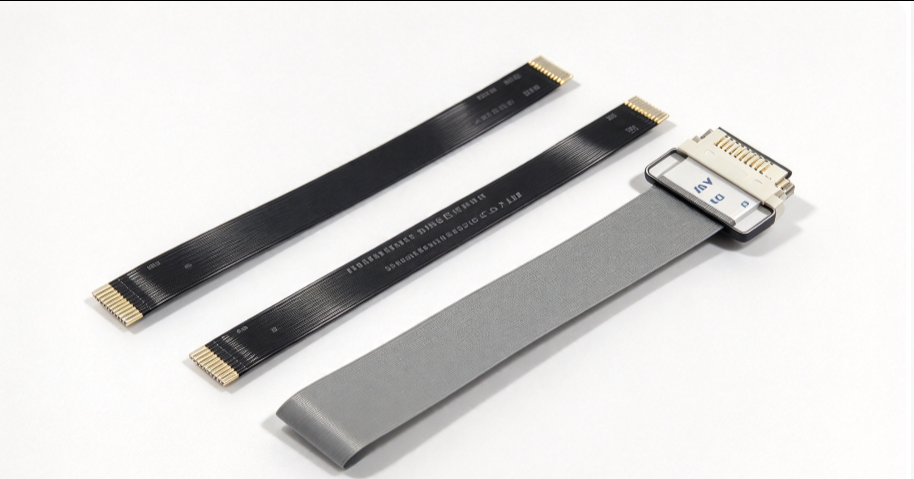
After splitting the conductors, each individual wire can be covered with a black rubber layer or a protective sleeve for extra insulation and mechanical protection. The covering is flexible, durable, and resistant to abrasion, oil, and chemicals.
Why use it:
- Protects individual conductors in harsh environments
- Adds flexibility for tight routing
- Withstands repeated flexing and mechanical stress
Typical applications: Medical devices, industrial equipment, automotive sensors
Aluminum Foil Shielded FFC
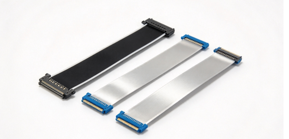
A layer of aluminum foil is laminated onto the FFC to block electromagnetic interference (EMI). The foil is typically bonded to one or both sides of the cable and can be combined with a drain wire for grounding.
Why use it:
- Reduces EMI and crosstalk in high-speed signal lines
- Protects sensitive signals from external noise
- Cost-effective compared to other shielding methods
Typical applications: LCD displays, industrial control panels, medical monitors
Electromagnetic Film Shielded FFC
Instead of aluminum foil, a thin electromagnetic interference (EMI) film is applied to the FFC. This film absorbs and suppresses high-frequency noise more effectively than standard foil in some applications.
Why use it:
- Superior high-frequency noise suppression
- Thinner and more flexible than traditional shielding
- Can be customized for specific frequency ranges
Typical applications: High-speed data lines, automotive electronics, precision instruments
Buckled or Punched FFC (Mounting Ears / Holes)
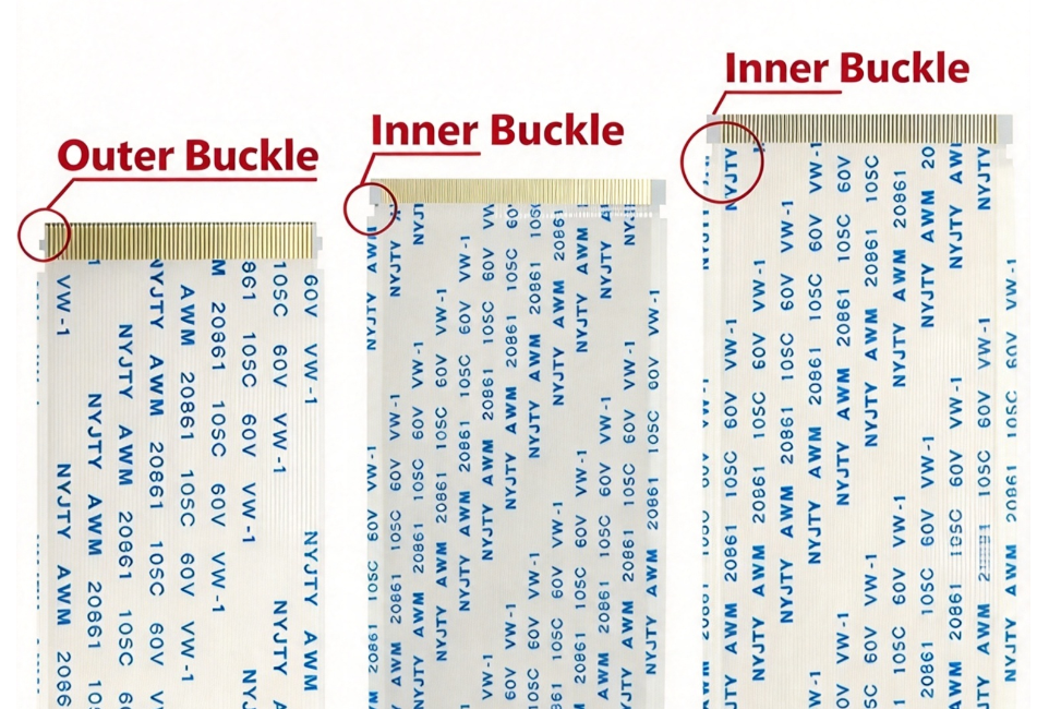
Standard FFC relies on the connector for alignment and retention. For applications that need extra mechanical stability — or where the cable must be fixed directly to a housing or chassis — we can add mounting ears (buckles) or punched holes to the FFC.
Three common styles:
- Outer Buckle — the ear extends from the outer edge of the cable, beyond the conductor area
- Inner Buckle — the ear is formed within the cable width, between the conductors
- Punched Hole — a hole is punched through the FFC for screw or post mounting
Why use it:
- Prevents the cable from shifting or pulling out during vibration
- Provides a fixed mounting point on the device housing
- Improves assembly accuracy and long-term reliability
Typical applications: Automotive electronics, industrial control panels, medical devices, and any application requiring secure cable fixation
These features are fully customizable — ear position, hole diameter, and cable width can all be tailored to your drawing.
How to Choose the Right Process
| Requirement | Recommended process |
|---|---|
| Standard board-to-board connection | Standard FFC |
| Independent routing at one end | Split FFC |
| Harsh environment, high temp | Black rubber or sleeve protected FFC |
| EMI protection, general | Aluminum foil shielded FFC |
| High-frequency noise suppression | Electromagnetic film shielded FFC |
| Multiple conductors + protection | Split + protected FFC |
These processes are fully customizable. If you have a specific routing, shielding, or environmental requirement, send us your drawing — our engineers can recommend the right FFC construction for your application.


Author

xl885479@gmail.com